
In this project
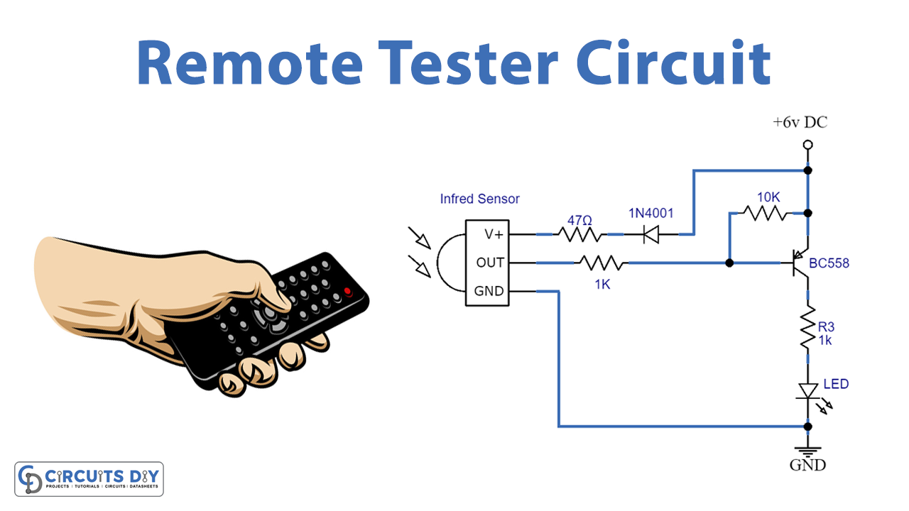
In this tutorial, we are making a Remote tester circuit. We all are familiar with our TVs, DVD players, music systems, and many other devices that are controlled through IR Remotes. There are different types of remote controls available for different devices and most of them work on a frequency signal of approximately 38KHz.
We usually check multiple times to find out if our remotes are working properly or not. So, this remote tester can be a good tool to check it. This tester circuit is using an IR Receiver sensor TSOP 1738. This IR sensor has a FET signal amplifier and a PIN photodiode enclosed in an Epoxy case. It operates on 5 volts, gives an active low output, and gives high output with no input signal.
Hardware Components
The following components are required to make the Remote Tester Circuit
| S.no | Component | Value | Qty |
|---|---|---|---|
| 1. | Breadboard | - | 1 |
| 2. | Connecting Wires | - | 1 |
| 3. | Battery | 6V DC | 1 |
| 4. | Transistor | BC558 | 1 |
| 5. | Diode | 1N4001 | 1 |
| 6. | IR Sensor | TSOP1738 | 1 |
| 7. | Resistors | 47Ω, 10K, 1K | 1, 1, 2 |
| 8. | LED | 5mm | 1 |
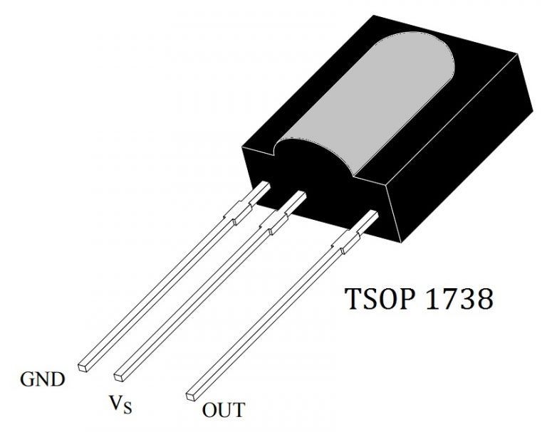
TSOP1738 Pinout

For a detailed description of pinout, dimension features, and specifications download the datasheet of TSOP1738
Remote Tester Circuit
Working Explanation
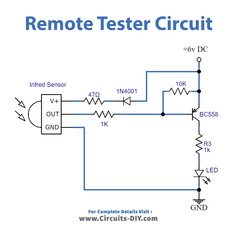
The operating voltage of this circuit is 6 volts. When an IR wave is received by the IR sensor its VO pin drops and its output changes from high to low. This will give the current to the base of the transistor and it will start conducting and the LED will glow. At each trigger signal from the IR sensor, the transistor glows the LED. This gives an indication of the remote is working properly.
The diode is used to drop 0.7 volts, giving the required 5V to the IR sensor from the 6V supply. A 47Ω resistor is used to limit the current going into the sensor. You can replace the transistor with others like BC158, BC177, or 2N905. This circuit can also be modified for sound indication by using a piezo speaker between the transistor’s collector and the negative terminal.
Applications and Uses
This circuit can test remotes of different devices such as Televisions, ACs, Media players/DVD players, etc.





Discussion
Be the first to comment