

In this project
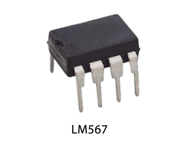
In this tutorial, we are making a project on a Proximity & Obstacle Sensor / Detector. The purpose of this circuit is to detect anything in its proximity, the circuit is built around a tone decoder chip LM567.
The internal circuitry of LM567 is designed to detect a specific input frequency ranging from 1Hz to 500kHz. This specific frequency on which the circuit will detect is set by setting a center frequency of the IC on the required frequency. This is done by using three components, when the center frequency is selected it will be set and extremely stable. There is also special internal circuitry in this chip for the rejection of the out-band signals and noise that makes it highly stable and makes sure not to produce a false output.
Hardware Components
The following components are required to make Proximity Obstacle Detector Circuit
| S.no | Component | Value | Qty |
|---|---|---|---|
| 1. | Input Supply DC | 5-9V | 1 |
| 2. | IC | LM567 | 1 |
| 3. | Transistor | 2N3904, BC327 | 1, 1 |
| 4. | IR Module | - | 1 |
| 5. | Resistor | 100Ω, 10KΩ, 12KΩ, 1KΩ, 470Ω | 1, 2, 1, 1, 1 |
| 6. | Ceramic Capacitor | 0.1µF | 2 |
| 7. | Electrolytic Capacitor | 1µF | 2 |
| 8. | LED | - | 1 |
LM567 Pinout
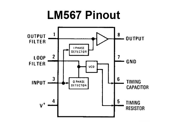
For a detailed description of pinout, dimension features, and specifications download the datasheet of LM567
2N3904 Pinout

For a detailed description of pinout, dimension features, and specifications download the datasheet of 2N3904
Proximity Obstacle Detector Circuit
Working Explanation
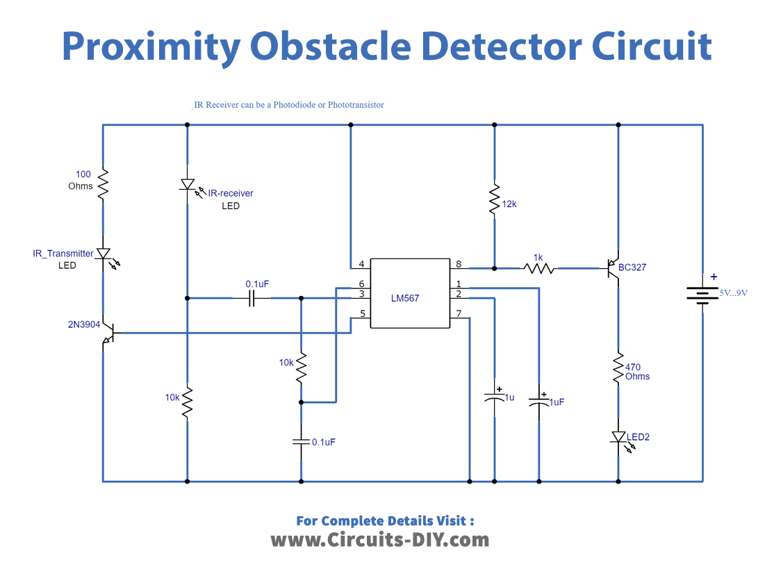
The operating voltage of this circuit is 5 to 9 volts DC this circuit will detect an IR signal that is produced from pin 5 of IC LM567. The IR transmitter LED sends an IR signal which is received by the IR receiver. When any obstacle is passed the IR signals will bounce back to the LED rather than to the IR receiver this will send a signal to the input pin 3 of the IC. when the received center frequency matches the signal of the output of the IC it gets a low or logic zero and the transistor BC327 will be activated. This transistor is acting as a switch for the LED so it will light up the LED.
Applications and Uses
This circuit has a lot of proximity detection applications in
- Robotic projects
- Electronic hands-free faucets
- Contactless switches





Discussion
Be the first to comment