

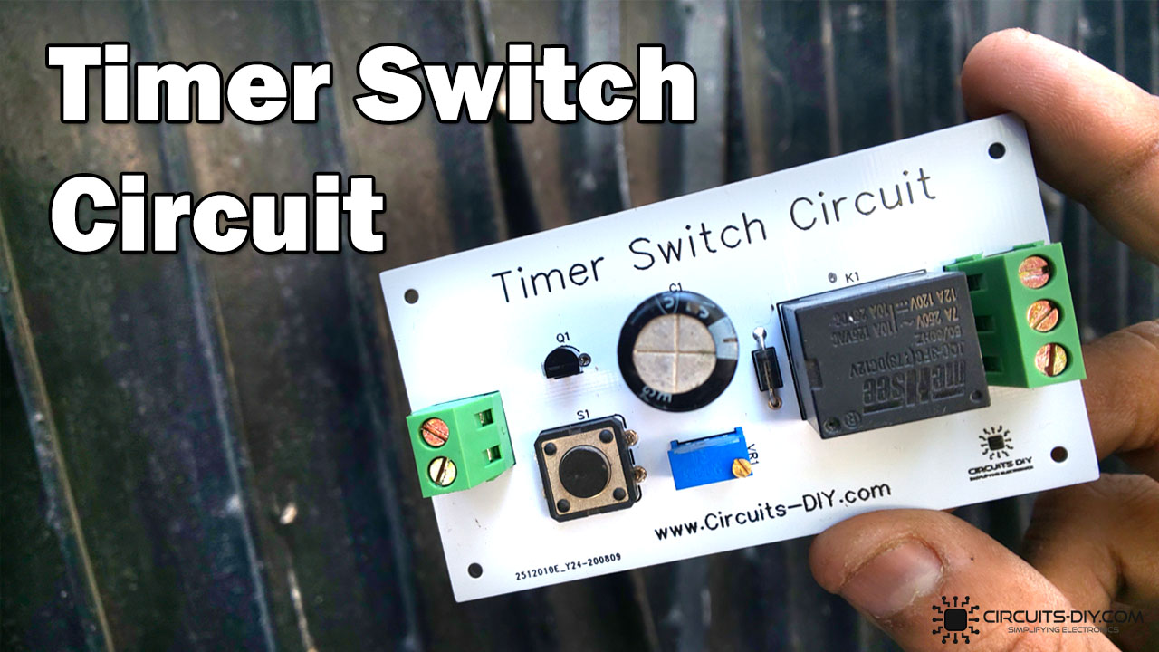
In this project
With the constant growth of the process control industry, the need and applications for On/Off delay timers is ever increasing. There are many industrial processes and tasks that would not be possible without the application of Relay based Timer Switches. A Relay based timer switch is a process control device that starts or ends a process with respect to the preset time defined by the RC time constant of the circuit.
It is generally used in controlling commercial or industrial-grade equipment such as HVAC equipment, traffic lighting, and large pumps. In today's tutorial, we will design a 12V Relay based Timer Switch Circuit Using a BC547 Transistor & a small number of other components.
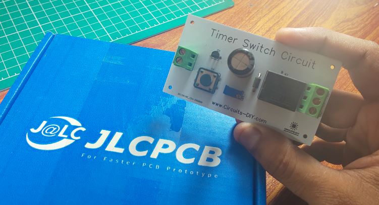
Hardware Components
The following components are required to make Timer Switch Circuit
| S.no | Component | Value | Qty |
|---|---|---|---|
| 1. | Relays | SPDT/5V | 1 |
| 2. | AC - DC Converter | 220V/12V | 1 |
| 3. | Transistor | BC547 | 1 |
| 3. | Block Connector | - | 1 |
| 4. | Potentiometer | 10K | 1 |
| 5. | Pushbutton | - | 1 |
| 6. | Capacitor | 1000uF | 1 |
| 7. | Diode | 1N4007 | 1 |
| 8. | Wall outlet with Plug | 220V | 1 |
| 9. | Soldering Iron | 45W - 65W | 1 |
| 10. | Soldering Wire with Flux | - | 1 |
| 11. | Veroboard | - | 1 |
| 12. | Jumper wires | - | As per need |
BC547 Pinout
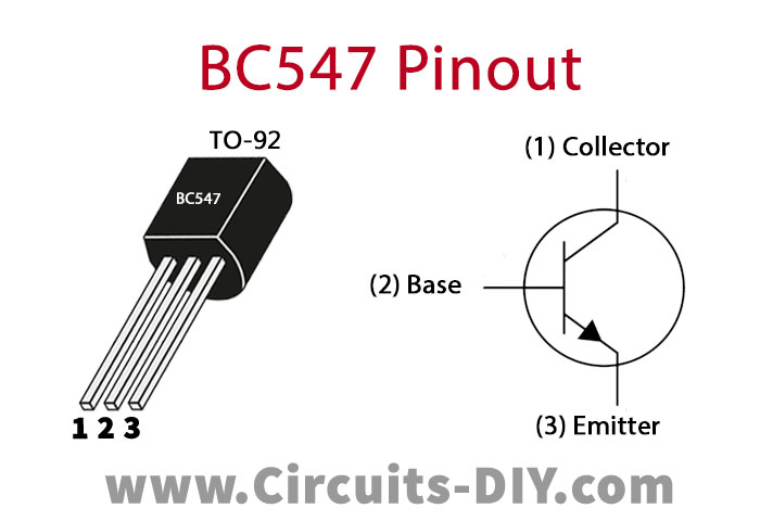
For a detailed description of pinout, dimension features, and specifications download the datasheet of BC547
Timer Switch Circuit
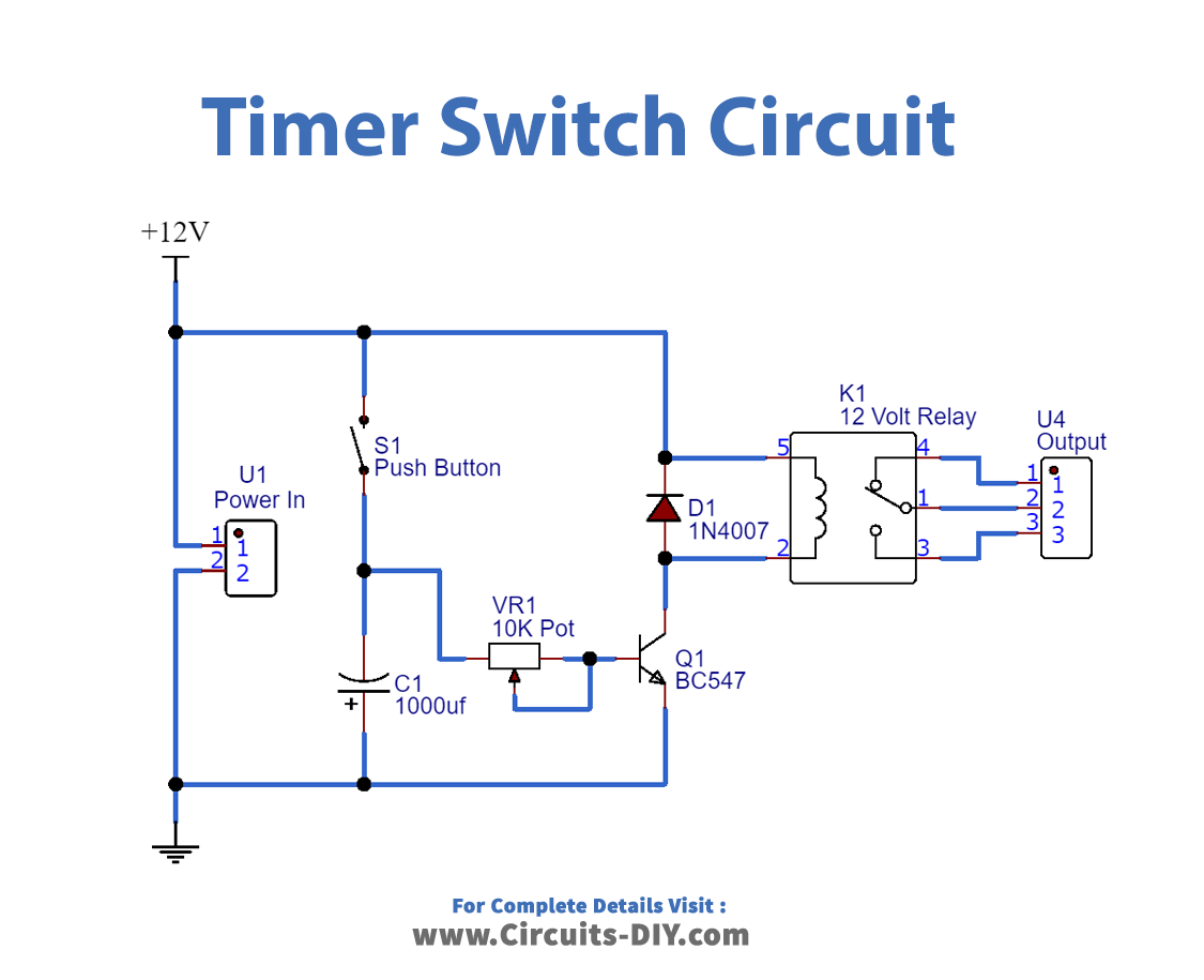
Application
- This circuit plays an important role in controlling many process control tasks such as automated control of AC and DC drives, sectionizing and criminalizing factory operations, etc.


Discussion
Be the first to comment