
In this project
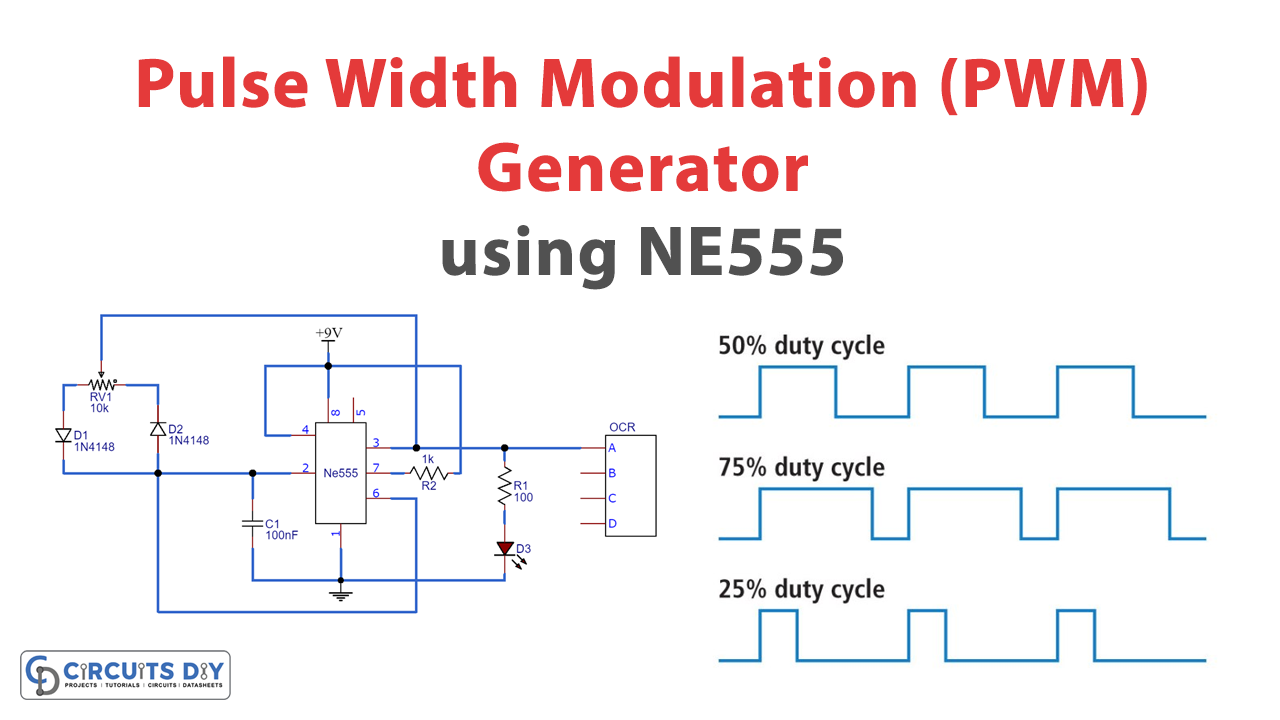
PWM (Pulse Width Modulation) is an essential feature of today's microcontroller because of the need to control many devices in almost every field of Electronics. 555 Timer IC is a highly convenient and versatile IC that you can use in many applications. Here we will use a 555 timer IC for generating PWM.
Pulse Width Modulation is a digital signal most commonly used in control circuits. It sets this signal high (5V) and low (0V) within a predetermined time and speed. Signal remains high during the on-time and remains low during the off-time.

Hardware Components
The following components are required to make PWM Generator Circuit
| S.No | Component | Value | Qty |
|---|---|---|---|
| 1. | Breadboard | - | 1 |
| 2. | Battery | 9v | 1 |
| 3. | Connecting Wires | - | 1 |
| 4. | IC | NE555 Timer | 1 |
| 5. | Potentiometer | 10k | 1 |
| 6. | Resistors | 100 ohm,1k | 1, 1 |
| 7. | Ceramic Capacitor | 100nF | 1 |
| 8. | LED | 5mm | 1 |
| 9. | Multimeter | - | 1 |
| 10. | Diode | 1N4148 | 2 |
555 IC Pinout

For a detailed description of pinout, dimension features, and specifications download the datasheet of 555 Timer
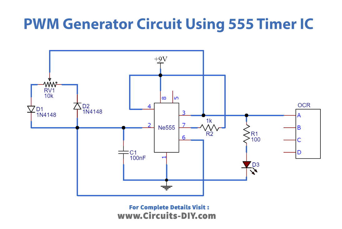
PWM Generator Circuit
Working Explanation
We have applied a variable resistor in place of fixed resistors to change the duty cycle of the output signal. Charging a capacitor through diode D1 and discharging through diode D2 will generate a PWM signal on the output pin of the 555 timers.
Application
We use PWM for motor controlling, lighting control, etc. At times we do not use a microcontroller in our applications. If we desire to make PWM without a microcontroller, then we go for some general-purpose ICs like op-amp, timers, pulse generators, etc.



Discussion 3
Thanks
Join the discussion