

In this project
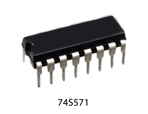
This Schottky memory is organized in the popular 512 words by 4 bits configuration. A memory enables input is provided to control the output states. When the device is en- abled, the outputs represent the contents of the selected word. When disabled, the 4 outputs go to the "OFF" or high impedance state. PROMs are shipped from the factory with lows in all locations. A high may be programmed into any selected location by following the programming instructions
74S571 Pinout
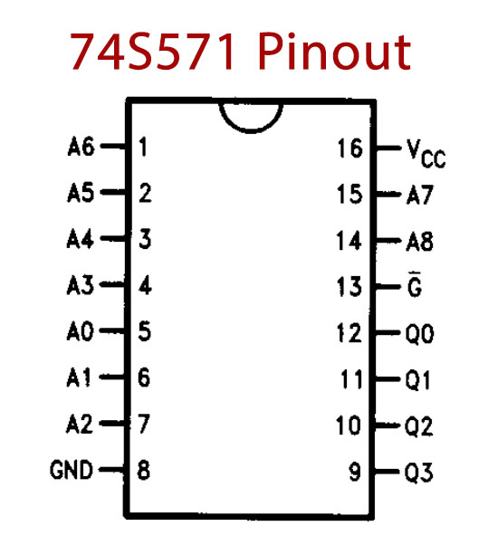
74S571 Pin Configuration
| Pin No | Pin Name | Description |
|---|---|---|
| 1 | A6 | Address Pin |
| 2 | A5 | Address Pin |
| 3 | A4 | Address Pin |
| 4 | A3 | Address Pin |
| 5 | A2 | Address Pin |
| 6 | A1 | Address Pin |
| 7 | A0 | Address Pin |
| 8 | GND | Ground Pin |
| 9 | Q3 | Data Output |
| 10 | Q2 | Data Output |
| 11 | Q1 | Data Output |
| 12 | Q0 | Data Output |
| 13 | G' | Output Enable |
| 14 | A8 | Address Pin |
| 15 | A7 | Address Pin |
| 16 | VCC | Power Supply Pin |
74S571 Key Features
- Advanced titanium-tungsten (Ti-w) fuses
- Schottky-clamped for high speed
- Address access down to-35 ns max
- Enable access-25 ns max
- Enable recovery-25 ns max
- PNP inputs for reduced input loading
- All DC and AC parameters guaranteed over temperature
- Low voltage TRI-SAFE programming
- TRI-STATE outputs
You can download this datasheet for 74S571 Tri-state PROM - Datasheet from the link given below:


Discussion
Be the first to comment