
In this project
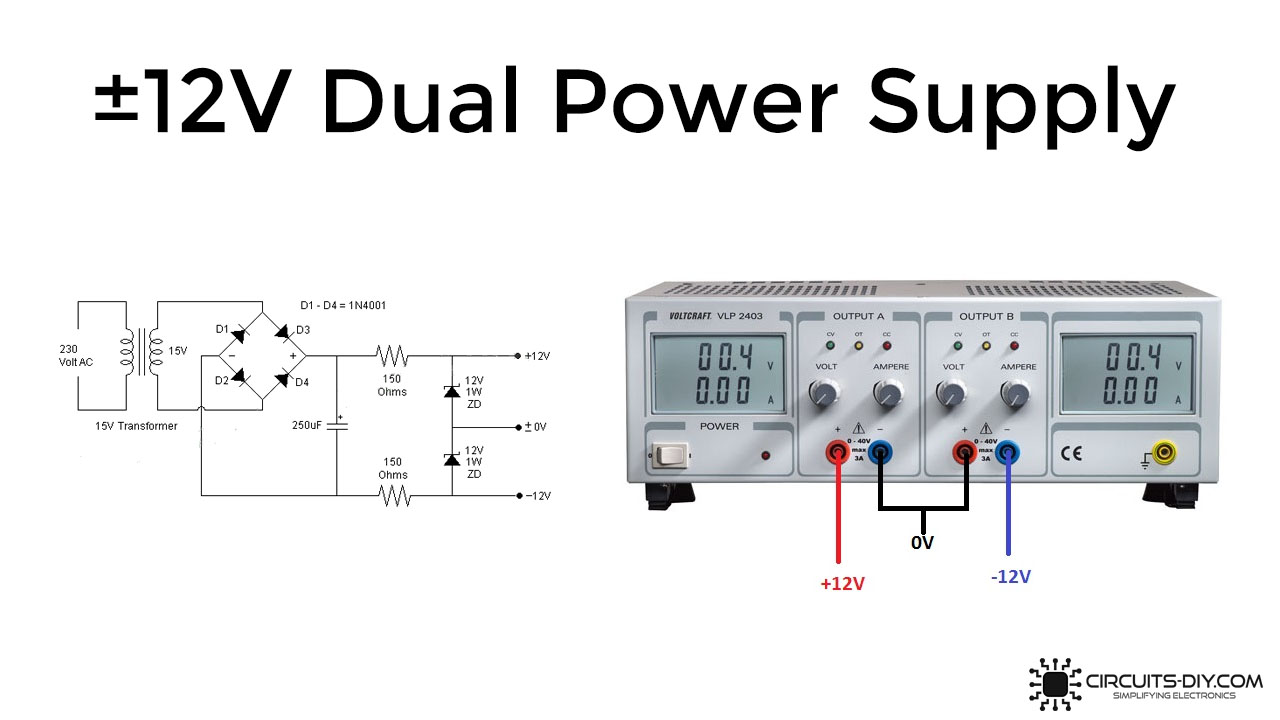
±12V Dual Power Supply is essential for electronic hobbyists & technologists nowadays. They provide a simple, easy & cheap source of a reliable DC supply. So, in this project, we are going to design a simple ±12V dual power supply using 12V/1W Zener diodes.
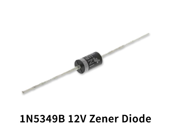
A Zener diode is a silicon semiconductor device that permits current to flow in either a forward or reverse direction. The Zener diode consists of a special, heavily doped p-n junction, designed to conduct in the reverse direction when a certain specified voltage is reached. Zener diode has a precise reverse-breakdown voltage, at which it starts conducting current, and continues operating continuously in the reverse-bias mode without receiving any damage.
Hardware Components
The following components are required to make 12V Dual Power Supply Circuit
| S.no | Component | Value | Qtyt |
|---|---|---|---|
| 1. | Step-down Transformer | 230V/15V | 1 |
| 2. | Zener Diodes | 12V/1W | 2 |
| 3. | Diodes | 1N4001 | 4 |
| 4. | Capacitor | 250uF | 1 |
| 5. | Resistors | 150 Ohm | 1 |
| 6. | Breadboard | - | 1 |
| 7. | Connecting Wires | - | 1 |
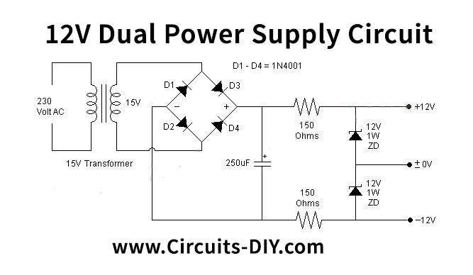
±12V Dual Power Supply Circuit
Working Explanation
The main component of this circuit is a 12V/1W Zener Diode. Here, the Zener diode is behaving as a voltage regulator. An input voltage of 230V is applied at the primary of the transformer which steps it down to 15V through mutual induction of the primary & secondary windings while maintaining the frequency at 50Hz. After which the 15V AC signal goes through a bridge rectifier (4x 1N4001 Diodes) which converts the AC signal into a rippling DC signal.
The output DC signal then goes through a 250uF smoothing capacitor in order to remove any residual noise. The DC signal then goes through 2 Zener diodes producing a regulated ±12V each. The property to have a constant voltage in the breakdown region enables Zener diodes to serve as a useful voltage regulator for low current uses.
Applications
- A Dual DC power supply can serve in applications such as applying a variable voltage to low-power DC motors.
- Commonly used in the testing of small electronic projects such as small DIY projects.




Discussion
Be the first to comment